|

Important info for laser users
Our patterns are exact to the mathematical size we quote as in 3mm equals a slot size of exactly 3mm we need to keep to this standard as our patterns get used by many people in many ways .A couple of very important things to know are
1: You must adjust the scale of the pattern so that the slot thickness is the exact thickness of the material you are cutting from. To achieve this you will need to measure your materials thickness using a set of digital calipers (these can be obtained inexpensively at any hardware store these days)
this is due to the fact that material is never the exact thickness the seller will tell you and you need to be accurate to 3 decimal points.
2. You can scale our patterns very accurately using our scale calculator program (it also is very inexpensive if you do not know the math to do the scaling )
this is the link
http://legacy.makecnc.com/scalecalc.php
3: you must allow for the kerf of you laser also when you scale the pattern to size this will be available from the manufacturer of you laser
and will also be controlled by how you focus the beam...i suggest cutting a couple of parts before doing a lot to test fit then you will be fine.
4: so if you work out what your kerf is and the exact thickness of material used you should be able to do the scaling in one go
test fit a couple of parts then after that you will be good to go an any of our patterns and will only need to change things if you change Materials
a rule of thumb is to always check material thickness even if you buy the same product from the same supplier each time you buy a new batch
NEW TO CNC ? CLICK HERE
Basic Information for CNC Cutting and Making makeCNC Projects Patterns and Puzzles.
You can download a PDF of the information on this page to print out and take to the shop just right click and save as at the link here CNC basics for 3d puzzles
Basic Information for CNC Cutting and Making makeCNC Projects Patterns and Puzzles.
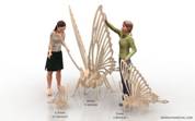 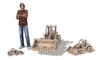 
Hello and Welcome.
The information presented here was written for people wishing to cut out our 3d puzzle projects and other makecnc projects and patterns. It is, however, applicable to CNC cutting in general and will be useful to people who are new to the CNC process and hobby. It does not necessarily follow industry best practices and makecnc is not responsible for how you use this information. Remember the golden rule, “safety first”.
Most makeCNC Projects that you will download from our site come in a compressed file called a zip file. This is a file that stores the individual files that make up and are needed for your project or projects. After you purchase and download the project, right click on the zip file, and click "Extract Here". The files are extracted to the folder on your PC where the zip file is, although later versions of windows have zip extraction built in some earlier versions do not and you may need to install some software to extract the files. The zip file manager we use is FREE and is called Winrar and it can be downloaded here:
http://www.rarlab.com/download.htm
Our DXF and EPS based projects are ready for you to create your tool paths with and cut out and process any pockets or dados as well as engrave any included details on after which you can assemble them using our comprehensive assembly guides where needed.
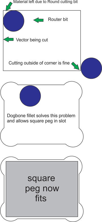
when you are making projects for your CNC router and cutting those projects out of sheet materials like plywood or acrylic or MDF you will have noticed that when your router bit comes to the inside corner of a vector or drawing you have made ,it leaves a small amount of material in the corner due to the radius of the router bit or tool you are using the picture below illustrates this.
TO TAKE ADVANTAGE OF DOGBONE FILLETS FOR ROUTER CUTTING YOU MUST USE A BIT HALF THE SLOTS SIZE OF THE SCALE YOU ARE CUTTING
`
another important point is:
Our patterns come in specific sizes meaning a pattern is perhaps cut from say a sheet of 1/8th plywood so the scale of the pattern is set to make the slots in the pattern that allow the parts to fit together to be set to that size eg .1250 inches = 1/8th inches.
But the issue is that when you buy plywood from a given supplier they may state that it is 1/8th when it is in reality a little more or less than that specific measurement.Which means when you cut the parts using a setting for .1250 (example) the thickness of the plywood will mean the slots may be a little to large or a little too small .What you should have done is measure the thickness of the ply with Digital Calipers before you created the tool paths so that you could rescale the drawings to set the slot sizes to the exact same size as the thickness of the material you are cutting.
There is a math formula to achieve this in your given CADCAM software but many people do not want to dally with it so we wrote a small program to deal with this that will do the calculations for you here is the link to it
http://legacy.makecnc.com/3d-scale-calculator.php
Please make sure you read the help files for the program before use
Also remember if you are cutting from CNC router versions of our files that have dog bone fillets then you should be using a bit that is half the size of the slot measurement or less to be able to take advantage of the fillets.
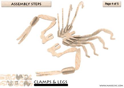
The information we provide here assumes at least a very basic knowledge of the CNC process. If you do not have that please see the learning section, New to CNC, on our website before proceeding with your project and the information presented here.
http://legacy.makecnc.com/newtocnc.php
The processes and tool paths you will use to cut and create the parts that make up your DXF or EPS based project can be broken down into a few simple tool path strategies.
We will give you a brief explanation of each to get you on your way.
Our projects are designed to be able to be cut on many sizes of machine so if you have a very small footprint CNC router you can still use our designs but you may have to use several smaller sheets of material to cut out all the parts and you would have break up the DXF into sections using your CAD or vector drawing software. It’s a simple task but remember many parts have internal slots and pockets in them so make sure to refer to your instructions that come with the project to be sure you keep the appropriate parts correctly grouped if you are breaking up DXF files to cut over several sheets of material.
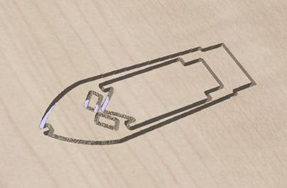
Software Used:
Tool paths to drive your CNC tool are created by the CAM software you use.
The files we provide or any files you feed into CNC machines need them. They are commonly referred to as strategies and from here on out that’s how we will refer to them.
For its ease of use, great support and inexpensive price point we use Vectrics Cut2D application for most of our 2d tool path generation and highly recommend it. They also have another more advanced product, V carve Pro, that adds design features and more advanced tool path features. There are many other options available from expensive to free. It’s really your choice.
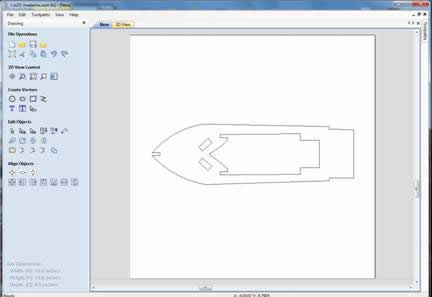
A couple of points about open and closed Vector lines in CNC Routing
Typically vector lines around parts for use in CNC cutting are closed meaning the line around the shape of the parts profile has no breaks in them. Open vectors will cause problems when trying to create profile tool paths to cut out parts and the breaks in these vector lines may be so small that you cannot see them with the human eye. makecnc projects have had this closing work done where needed as part of our product creation process. This is one of the things that makes a good quality CNC project as opposed to finding free DXF files and puzzles on the net which have many broken lines and distortions in the vectors, and in most cases jaggy circles and lines instead of smooth curves and arcs. These jaggy lines etc are caused by vectorizing from scanned pictures rather than drawing models from scratch and while the designs may look ok from a distance, in most case the parts are so distorted they will not even match and fit together after cutting them out. So be aware of this when you see these files out and about.
The time when open vectors can be machined is when adding line detail to a project using a V-bit as in the diagram below:
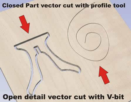
Tool paths and Safety:
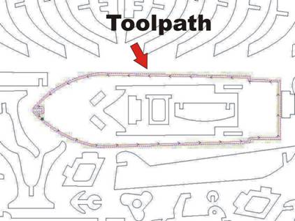
When you cut out your parts you need to think about how to create your tool path strategies. Most of the designs we have unless otherwise stated in the included documentation follow a simple set of rules when it comes to tool path strategies.
You will also need to think about how you are holding your parts down to the router table surface while you are cutting them or creating pockets and engraving parts etc. There are many ways to achieve this and we do not promote any one way to get the job done. There is some information on this at our website in the learning pages but new ideas and methods are being created every day so we leave it up to you to find the best solution for your work. We do warn you that CNC machines can be dangerous and flying parts that were not well secured after cutting can injure you badly so please do not take this important step in the CNC process lightly and make sure you think your holding strategy through before attempting to cut your parts.
Bit Sizes:
TO TAKE ADVANTAGE OF OUR DOGBONE FILLETS FOR ROUTER CUTTING YOU MUST USE A BIT HALF THE SLOTS SIZE OF THE SCALE YOU ARE CUTTING
We recommend using certain size bits to cut our projects but this is not a rule in stone. You can use smaller bits to cut larger slots or thickness of material to achieve better details in your work.
For instance you may have a bear puzzle that is made from 1/8th inch thick plywood and the slots are sized in such a way that you can cut the project using a 1/8th inch bit. But if you look closely at the bear you might see he has sharp teeth and small details you would like to see in the end result but they will be lost if you use a 1/8th bit as the radius of the tool will not fit into some of the tiny details of the vector drawing. In saying this I should remind you that we design our projects to look good with the recommended bit size but we leave in the smaller details for those of you who want a more detailed look to be able to achieve this using smaller bits that can fit the inside parts of this detail as shown in the diagram.
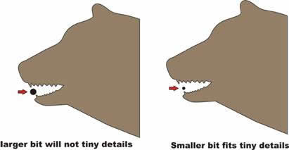
But remember, if you choose these options you need to create tool path strategies that allow you to do this successfully and you need to understand the feed and speed rates of these tiny tools or you will be breaking many tool tips. With careful thought and planning really nice results can be obtained.
Cut Sequence:
So that you have the most efficient holding of parts, it is important to process and cut the parts in the correct sequence using the right tool for the job.
For profiling and pocketing (area clearing) you will normally use the same tool/bit. See our bits section on the website for recommendations. For bits to process different materials for engraving details you would normally use a V-shaped bit.
Typically, the engraving part of the process would be done first as the material you are cutting from will be strongest at this time.
You would then machine the pockets or full slots second for the same reason
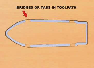
And finally, the profile of the parts would be cut to allow you to remove the part from the material. Many users software allows the creation of bridges in their tool path strategies and these help to hold the parts in place in the material so you can carefully cut the bridges later and remove the parts from the material. You will need to have a very flat surface on your table if you use this method. If you use thin sheet material like 1/8th ply as your bridges they will only be about a 1/16th thick so keep this in mind. For very thin material I have had success with slow feed rates and double sided tape and, of course, safety glasses.
Engraving and Cutting Profiles:
Machine along a Vector.
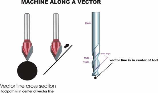
For any detail engraving using a V-bit we would machine along the vector itself with the tip of the bit pointing directly at the center of the vector line and in most cases a set depth of cut to achieve the result required. This is similar but not totally like the V Carving that is used in 2.5D machining and can be achieved using Cut2D. There are other types of V-bit carving that V carve Pro uses where the depth of cut can vary but these are not currently used in our 3D puzzle projects. These vector lines are very thin so to illustrate this I have shown a V-bit tool and a thickened vector line as an example in the diagram below.
Detail vectors may be open line
Sometimes it is necessary to machine along a vector using a tool that has a thicker cutting tip (radius) like an end mill normally used in profiling and pocketing. In this case machining along a vector will set the line to the center of the tool as illustrated.
Machining on the Inside of the vector:
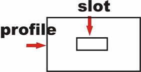
This is where the profile tools outer edge will machine along the inside of the vector line. This allows the user to cut out the hole slot or desired shape to the size that is set in the drawing where if the user machined on the outside of the vector then the hole or slot they cut would be too big by the size of the tools radius. Again, how the waste material is held to the table after the cut is processed is a concern and needs to be thought out as you do not want material flying out of the part to injure yourself or people nearby. In our puzzles the amount of the tool radius leaves a round end in the slots. This does not pose a problem when fitting together these puzzles as it is a relatively small amount of over size in the length of a slot. Other strategies exist to deal with square parts fitting into round holes and these are called dog bone fillets. More information on those is available on our site in the learning pages but these dog bones are not needed for these types of projects in smaller sizes.
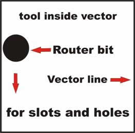
Machining on the inside of the vector ensures that the slot hole or shape you need to cut from the inside of a profile drawing is the exact size of the part drawn inside the profile drawing.
Pocketing or Area Clearing the Inside of a Vector:
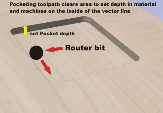
Your CAD CAM software will have a different tool path strategy for pocketing and area clearing of material. Pocketing is when you need the tool to remove a certain amount of material to a specific depth in the material but not all the way through and is used in our puzzles and projects on occasions when we need to create parts that have a positive and negative part that needs to fit together. Our instructions will show you where these are needed if they are part of the particular project you are working on.
Positives and negatives are closely related to how inlay works and we will be talking more about that in other projects that use inlay or similar procedures but for 3D puzzles mostly just basic pocketing is required in a few cases.
Machining on the Outside of a Vector:
When cutting the final part from the sheet of material you need to create a tool path that machines along the outside of the vector as shown in the diagram. You also need to take into account that this final tool path will mean the part, if it has no bridges, will come loose from the sheet material and if no hold down strategy is in place can fly out of the part and at the very least damage the part or at worst damage you.
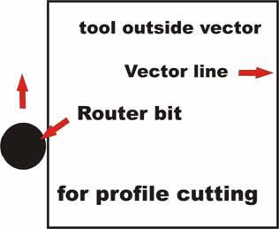
Machining on the outside of the vector ensures that the part is the exact size of the profile of the part in your DXF drawing.
WHAT IS A DOGBONE FILLET ?
TO TAKE ADVANTAGE OF OUR DOGBONE FILLETS FOR ROUTER CUTTING YOU MUST USE A BIT HALF THE SLOTS SIZE OF THE SCALE YOU ARE CUTTING
All makeCNC Products come with two types of files.
Laser ready and CNC router ready why ? whats the difference ? let me explain
when you are making projects for your CNC router and cutting those projects out of sheet materials like plywood or acrylic or MDF you will have noticed that when your router bit comes to the inside corner of a vector or drawing you have made ,it leaves a small amount of material in the corner due to the radius of the router bit or tool you are using the picture below illustrates this.

This concludes our basic introduction to cutting project parts on your CNC machine. It is not the only way to do things and perhaps not even the best way but it works and we have had great results using these strategies. If you have suggestions or information you think may help our customers to better enjoy our projects please email us your ideas and we will look at incorporating the good ones in future documents and web pages like these. This hobby is fast growing and open to ideas so Get Cutting and MakeCNC!
Thanks!
Paul and Julie Campbell
legacy.makecnc.com
copyright2011 makecnc.com LLC Delaware USA
|
